
Circuit diagram:
Diameter was chosen for the easy2led.com M25 housing - 24mm (or larger). For (my) "Magic-shine"-type housing - better make the board larger (i.e., grind off less). Also, the PCB diameter almost equals (a bit larger, by 2mm) to the holder diameter of a 20-mm lens, so that one can make a sandwich (holder-star-PCB) inside some cylindrical housing (see brake light).
(reminder, no buttons on the PCB - they are assumed to be external)
To estimate battery charge, its voltage is simply measured. No attempts to measure the charge itself, or take the history into account (under heavy load will surely lie.. just keep it in mind). Voltage measurement uses the buttons controller pins. When not measuring, there's no current.
Controller can be soldered in both PDIP (bigger), and SOIC (smaller SMD) package. I also ground off a bit the outer pins of my PDIP package.
There may be 1, or 2 info-LEDs on the board. The solder pads for both of them are conveniently located at the center.
To power them, solder pads for 2 current mirrors are provided - to make current less dependent on battery voltage. There are great current sources, like CAT4002A, MAX1916, FAN5612, TLC59731, PT4401E, but they all are not readily available to buy, and I prefered instant availability (I soldered some components out of old PCBs) over implementation efficiency. PNP-transistors (they are rarely-found on PCBs) - to make info-LED connected to ground, just like buttons (so there'll be 4 external wires). Of course, for software-control of 2 LEDs you'll have to free one controller pin: either make 1-channel control of power LED, or use RESET pin (and high-voltage programming).
Alternatively, the pads for transistors of the 2nd current mirror can be used for more efficient implementation of the 1st (1 in, 3 out) - you'll need to cross-scratch one trace, and solder external wires - I did this. Or one can make a "glowworm" - very dim (few uA), but always on light. There are many possibilities here (programmable or not, on separate LED or on info-LED, power from current mirror or thru a resistor..)
8 linear regulators are assumed to be controlled with 2 channels, 2+6. This gives a weaker minimal brightness (good for a low-power tactical purposes), makes turn on/off smoother, and also increases somewhat efficiency factor. I altered the connection to be 1+7 (cross-scratched 1 trace, and soldered a wire). But even this, on minimum, if straight into the eyes - somewhat blinds.
The control traces for regulators are routed such that if connection is 1+3 (e.g., for XPG LED), the regulators will be located symmetrically at the corners of a square.
The circuit for voltage measurement was wrong (my fault). I assumed there to be a FET Q1 instead of the diode D3. But no problem. Just solder a diode on the pads for Q1. No need to do anything with the board (scratch traces, or solder additional wires).
There are holes for soldering the power (3A) wires, 2 for ground, 2 for the LED. There are also 2 holes for strain relief of (thin) signal wires, or if you need to route an external wire from one side to the other.
How the PCBs look:

The below notes are mainly for people who considers building on/upon this driver, unnecessary for most.
There are pull-up resistors Rpu on each pin, and they can be enabled or disabled individually. They apparently affect the voltage the controller measures. The value of Rpu is not guaranteed, according to datasheet - 20-50k, so for PINB3 it's better to disable it (=do NOT do PORTB|=_BV(PINB3); do it for PINB4).
When connecting buttons to both headlights, the resistors couple in parallel. So if you plan to use headlights both coupled and independently, you'll want to use same resistors in both. Otherwise when headlights are connected, voltage levels will be different from when they are separate.
To re-program the controller you'll need the regulator-controlling pins. This means the power LED will blink using huge (3A) current. My Atmel STK500 board doesn't program at such current (0.5A max). So I took the wire from the RC-filter (the controller power supply filter) outside the housing, and soldered it to battery "+" wire *outside* - so that later I could de-solder it and re-program with normal, few-mA-current.
However, I discovered later, that if connecting all the necessary for programming wires, *except the ground*, the programming goes thru (the power LED blinks really dim) - *with* that above controller power wire soldered outside. So no need to de-solder it, just don't connect ground. But this is an undocumented hack, your mileage may vary.
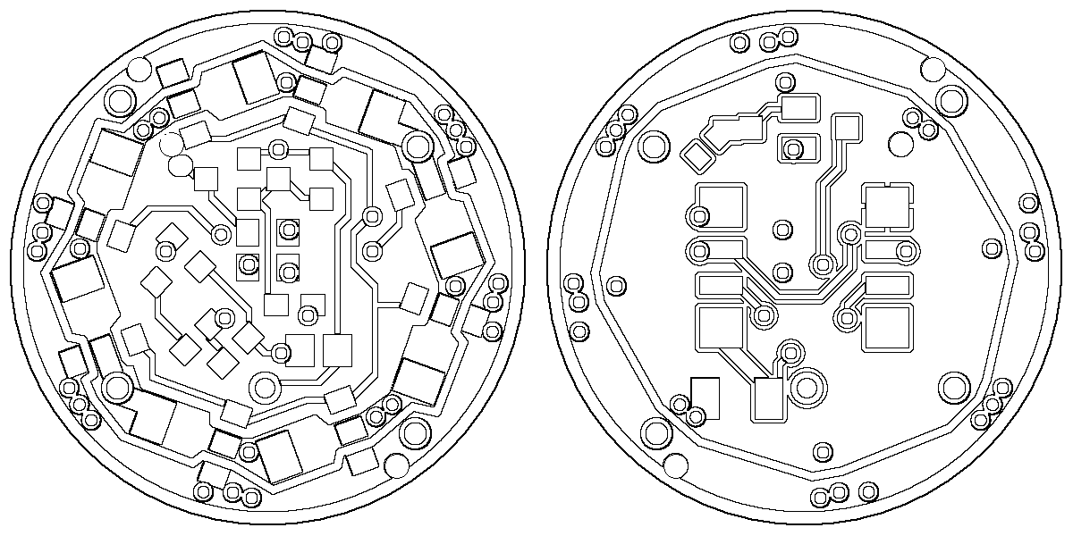
This black-and-white image: images/pcb-both_sides-bw.png shows how the elements' solder pads are positioned, and how the traces are routed. Generated (see pcb/notes/misc_notes.txt) to be printed at 600dpi - then the scale will be 1:1. Alternatively, one can measure distances in a graphical editor, and convert into mm/inches.
PCBs were fabricated by itead.cc. In my opinion - quality is superb. But there seems to be some changes with them from the 2014 New Year: they stopped responding in their forum. I don't know what's up with them.
As a test, I blew 0.3A thru a single thin trace - was not heating at all.
UPD, Nov 2016: Two controller pins are overloaded with two functions: buttons and voltage measurements. This means that sometimes, when "another" headlight is "pressing" a button to measure voltage, a short fake press may register by "this" headlight. Such fake "presses" need to be ignored in firmware, so the programming and debugging gets more complicated. So, for my case, when headlights are connected in paralell to buttons, this my clever idea with pins overloading turned out to be a headache. Bottomline: If you plan to change buttons control in the firmware a lot - better re-design the board for a controller with more pins, to move voltage measurements to separate pins (and modify firmware appropriately). If not - it's all good - no bugs appear anymore.